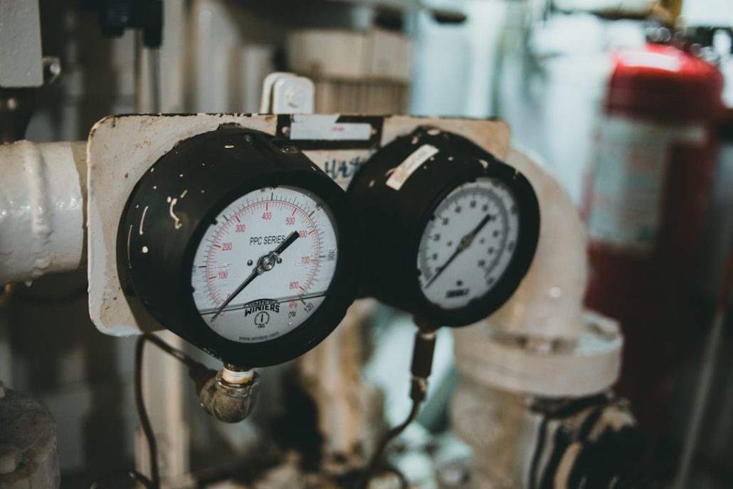
Understanding TXV Operation and Why Valves Fail
Thermostatic expansion valve repair and replacement requires safely recovering the refrigerant, unbrazing the old valve and filter-drier, brazing the replacement TXV under a nitrogen purge while heat-shielding the valve body, securing and insulating the sensing bulb on the suction line, leak testing, pulling a vacuum under 500 microns, and recharging to factory specifications.
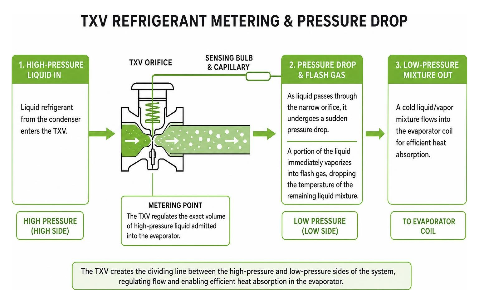
In any marine air conditioning circuit, the thermostatic expansion valve serves as the precise dividing line between the high-pressure and low-pressure sides of the system. While the compressor circulates refrigerant and the condenser rejects heat into raw seawater, the TXV regulates the exact volume of high-pressure liquid refrigerant admitted into the low-pressure evaporator coil.
As liquid refrigerant passes through the narrow orifice of the valve, it undergoes a sudden pressure drop. This drop causes a portion of the liquid to immediately vaporize into flash gas, dropping the temperature of the remaining liquid mixture. If you find yourself fixing your boat’s AC TXV valve, understanding this thermodynamic balance is key to ensuring your vessel maintains stable cooling during humid cruising conditions.
How the Metering Device Regulates Superheat
The TXV functions as an automatic mechanical brain for the evaporator. It constantly balances three distinct forces to maintain a stable target superheat (typically between 5°F and 15°F at steady state):
- Bulb Pressure ($P_1$): Exerted downward on the top of the internal diaphragm by the charge within the sensing bulb and capillary tube, acting to open the valve as the suction line warms.
- Evaporator Pressure ($P_2$): Exerted upward against the bottom of the diaphragm, acting to close the valve when suction pressure rises. In an internally equalized valve, this pressure is sensed directly at the valve outlet. In an externally equalized valve, a separate line references pressure downstream of the evaporator coil to account for internal coil pressure drops.
- Spring Pressure ($P_3$): A mechanical spring acting alongside the evaporator pressure to push upward and close the valve needle.
When these forces remain in equilibrium, the refrigerant completely boils off into a vapor before leaving the evaporator, picking up just enough sensible heat to guarantee that no destructive liquid droplets reach the compressor.
Common Causes of TXV Blockage and Failure
Because expansion valves feature microscopic internal tolerances, even microscopic contaminants can compromise operation:
- Moisture Contamination: Moisture circulating in the refrigerant oil freezes instantly as it expands through the valve port. The resulting ice crystals physically plug the orifice.
- Sludge Accumulation: Thermal breakdown of compressor oil, combined with trace moisture, creates acidic sludge that gums up the internal needle and seat.
- Paraffin Wax Buildup: Certain non-compatible or degraded lubricants precipitate wax at low evaporating temperatures, choking flow.
- Acid Buildup and Copper Plating: Acidic conditions strip metal from piping and deposit copper film directly onto precision valve stems.
- Mechanical Wear and Corrosion: Constant maritime vibration, combined with humid salt air in tight bilge spaces, can crack capillary tubes or corrode external adjustment assemblies.
Warning Signs and Diagnostics for a Malfunctioning TXV
When a TXV loses its calibration or physically binds, cooling performance drops sharply. Yacht owners often notice the air handler blowing tepid air, ice blanketing the copper lines, or the compressor cycling off on thermal overload. Recognizing these early symptoms prevents extensive system damage when your boat air conditioning stops cooling in the middle of a trip.
For a broader breakdown of symptom patterns, reviewing Thermostatic expansion valve troubleshooting methods can clarify whether an issue is mechanical or related to airflow.
Diagnostic Testing for Thermostatic Expansion Valve Repair
Accurate diagnostics require measuring operating pressures and line temperatures simultaneously rather than guessing based on sight alone.
- Measure Operating Pressures: Connect a calibrated digital manifold gauge set to the liquid line and true suction service ports.
- Calculate Evaporator Superheat: Convert the suction pressure reading to its saturated evaporating temperature using a PT chart. Subtract that saturated temperature from the physical pipe temperature measured at the evaporator outlet.
- Calculate Condenser Subcooling: Convert the high-side liquid line pressure to saturated condensing temperature, then subtract the actual liquid line surface temperature.
- Analyze Pressure Differential: Compare the split between high-side liquid pressure and low-side suction pressure against manufacturer baseline charts.
A restricted or stuck-closed TXV typically produces high superheat, normal to high subcooling, low suction pressure, and reduced amp draw on the compressor. Conversely, an overfeeding valve exhibits low or nonexistent superheat and elevated suction pressure.
Identifying Valve Hunting vs Stuck Needles
A common issue encountered in marine climate control is valve hunting, where the valve continually overfeeds and underfeeds in an unstable cycle. This often stems from thermal lag when a sensing bulb is loose, uninsulated, or mounted where oil pools along the suction pipe.
| Condition | Suction Pressure | Superheat Value | Evaporator Behavior | Risk to System |
|---|---|---|---|---|
| Stuck Closed / Starved | Abnormally Low | Excessively High (>20°F) | Coil starved; line icing near inlet | Compressor overheating; low airflow capacity |
| Stuck Open / Flooding | Abnormally High | Near Zero (<3°F) | Entire coil cold and sweating heavily | Liquid slugging; permanent compressor valve failure |
| Valve Hunting | Fluctuating Widely | Swings erratically | Alternating sweat and frost patterns | Thermal instability; premature mechanical wear |
Professional Thermostatic Expansion Valve Repair and Replacement Steps
Replacing a failed marine expansion valve requires strict adherence to clean refrigeration practices to prevent premature failure. Following established TEV installation specifications ensures the replacement maintains system balance.
Tools Needed for Thermostatic Expansion Valve Repair
- EPA-compliant refrigerant recovery machine and DOT recovery cylinder
- Digital manifold gauge set with temperature pipe clamps
- Oxy-acetylene or portable MAP-Pro torch kit with 15% silver brazing alloy
- High-efficiency two-stage vacuum pump and digital micron gauge
- Dry nitrogen regulator and purge assembly
- Wet thermal heat-sink wrap or heat-blocking gel
- Calibrated torque wrench for mechanical flare connections
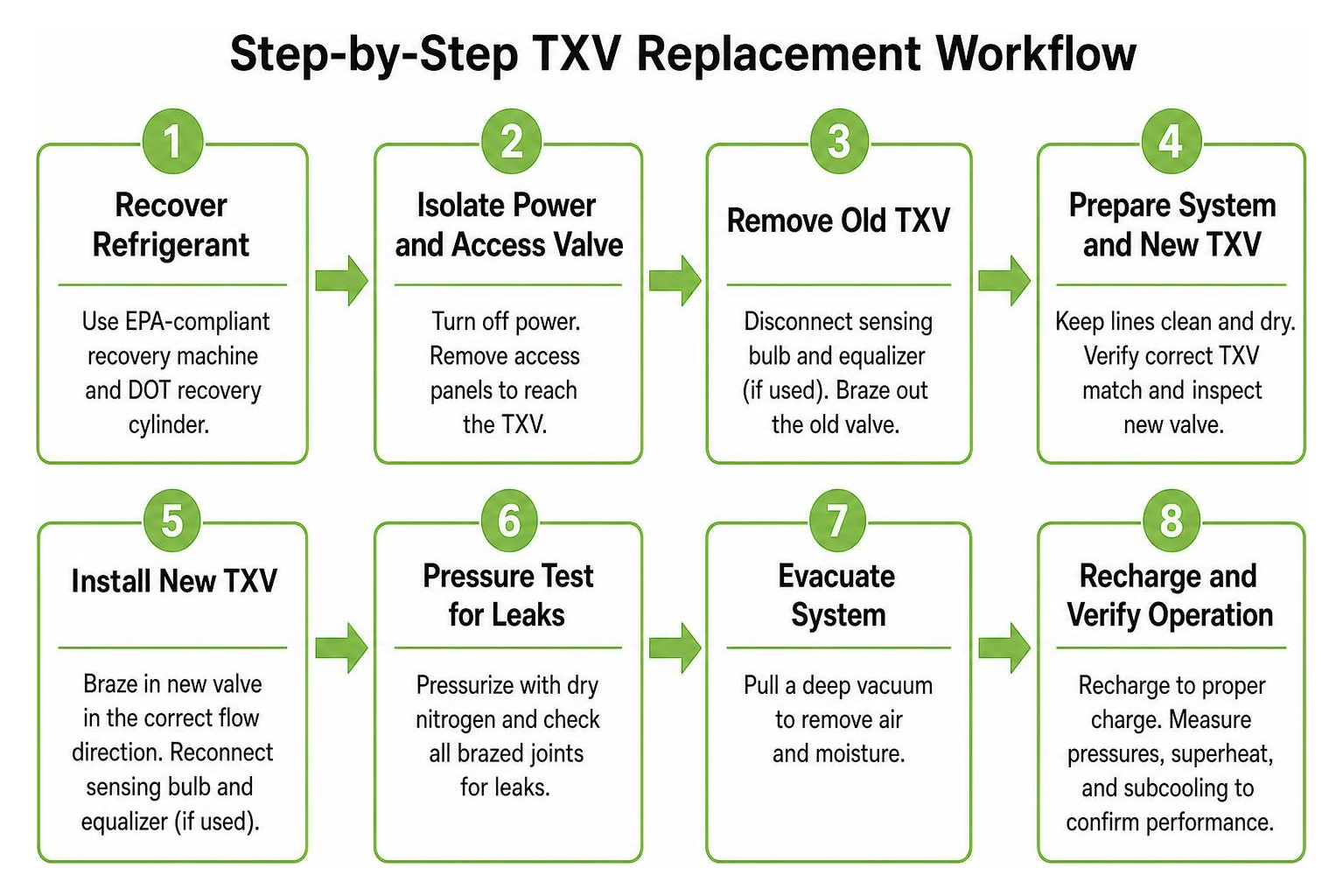
Step-by-Step Valve Removal and Installation
- Refrigerant Recovery: Disconnect power, lock out electrical breakers, and recover the complete refrigerant charge into an approved recovery cylinder using clean recovery equipment.
- Unbrazing the Old Valve: Remove the old sensing bulb and equalizer line. Wrap the nearby copper lines and surrounding marine bulkhead with fire-retardant heat shields. Apply a wet rag over the valve body and unbraze the inlet and outlet joints using a concentrated flame.
- Filter-Drier Replacement: Cut out and discard the existing liquid line filter-drier. A new filter-drier must always be installed whenever the refrigerant loop is unsealed.
- Braze the New Valve: Flow a low-pressure dry nitrogen purge (3–5 PSI) through the tubing to prevent internal copper oxide scaling. Wrap the new valve body in a saturated cold cloth to protect internal seals and superheat springs. Braze all connections using 15% silver alloy, avoiding direct torch contact with the power head.
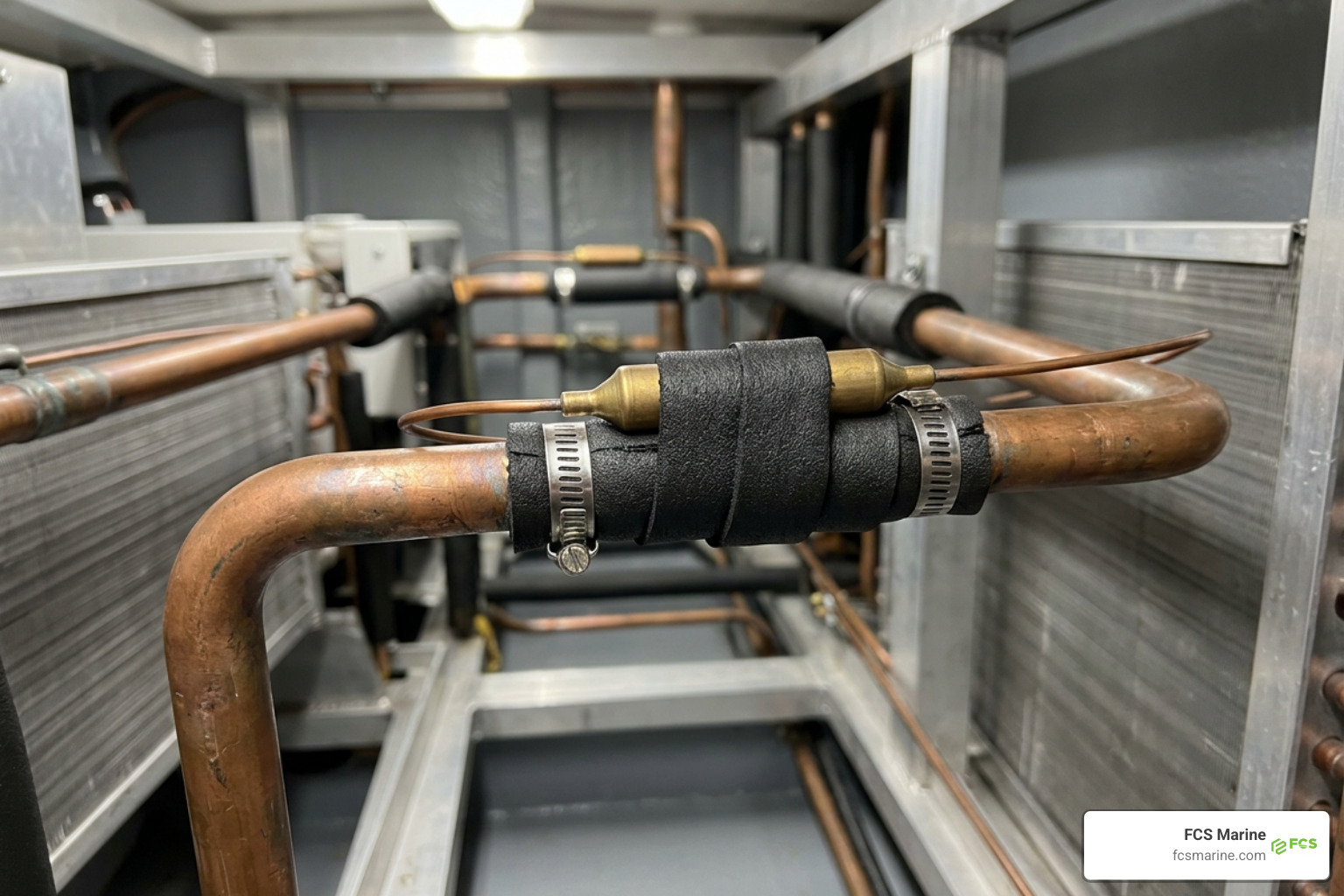
- Position the Sensing Bulb: Clean the suction line to bare copper. Clamp the sensing bulb tightly on a horizontal section of the suction line within 3 to 6 inches of the evaporator outlet. Position the bulb at the 12 o’clock position for small lines (under 7/8″) or at the 1 to 4 o’clock position for larger lines to prevent reading pooled compressor oil. Never mount the bulb on a vertical riser or downstream of an oil trap. Insulate the bulb completely with moisture-resistant foam tape.
- Equalizer and Leak Test: Secure the external equalizer line upstream of the bulb. Pressurize the sealed circuit with dry nitrogen to 150 PSI and perform electronic and bubble leak tests across all joints.
- Evacuation and Charging: Pull a deep vacuum until the digital micron gauge reads below 500 microns with a stable decay test. Recharge the system with virgin refrigerant by weight to exact OEM nameplate specifications, then verify steady-state superheat and subcooling.
Preventive Maintenance to Protect Expansion Valves
Consistent preventive care shields sensitive metering components from premature contamination and mechanical strain. Keeping an updated marine AC maintenance checklist helps track operating parameters and catch system abnormalities early:
- Inspect Filter-Drier Indicators: Regularly inspect the liquid line sight glass for color changes indicating moisture ingress, or bubbles indicating low subcooling or liquid line restrictions.
- Maintain Clean Air Filters: Wash or replace return air filters every month. Restricted evaporator airflow lowers coil temperatures, which can induce false valve hunting and mimic metering failure.
- Check Capillary Lines: Inspect the capillary tube running from the power head to the sensing bulb for signs of fretting, kinks, or contact with vibrating machinery components.
- Conduct Annual Acid Tests: Test compressor oil during seasonal maintenance to detect trace acid before it etches metal surfaces or clogs internal valve ports.
Frequently Asked Questions About TXV Replacement
Can a thermostatic expansion valve be cleaned instead of replaced?
In most modern hermetic or compact marine AC systems, the TXV power element and internal pin assembly are sealed units. If contamination involves wax or foreign debris trapped in an accessible inlet strainer screen, that screen can sometimes be cleared after system evacuation. However, if the internal diaphragm has lost its charge, the internal spring has fatigued, or acid has scored the seat, full replacement is the only reliable solution.
How much does it cost to replace a TXV?
Total replacement costs depend on system capacity, refrigerant type (such as R410A or legacy blends), physical accessibility within the vessel’s cabinetry, and the required labor time to recover, braze, pull deep vacuums, and recharge. Because the refrigerant circuit must be unsealed, replacing the liquid line filter-drier is also included in the overall service scope.
How long does a typical expansion valve last?
Under clean, well-maintained operating conditions, a quality expansion valve can operate reliably for 10 to 15 years. However, in demanding marine environments, excessive vibration, severe seawater heat exchanger fouling, or unresolved moisture contamination can degrade valve internals within a shorter operational window.
Conclusion
A properly functioning thermostatic expansion valve protects the compressor from liquid slugging while extracting maximum cooling capacity from every pass of refrigerant through the evaporator. When valves stick, starve, or lose calibration, resolving the problem promptly restores dependable climate control throughout your vessel’s living spaces.
Because TXV service requires specialized recovery machinery, nitrogen purging, and precise superheat calibration, yacht owners across South Florida count on experienced technicians to handle these repairs. FCS Marine provides professional on-site yacht service, traveling directly to where the vessel is berthed across Palm Beach County, Broward County, Miami-Dade County, Martin County, St. Lucie County, Fort Lauderdale, and Pompano Beach.
Whether you need detailed system diagnostics or comprehensive marine air conditioning support, our mobile team brings complete diagnostic and brazing capabilities directly to your slip. Contact FCS Marine today to schedule your vessel’s AC inspection and ensure your cooling system performs reliably all season long.